EQUIPMENT
Simulation, measurement and prototyping
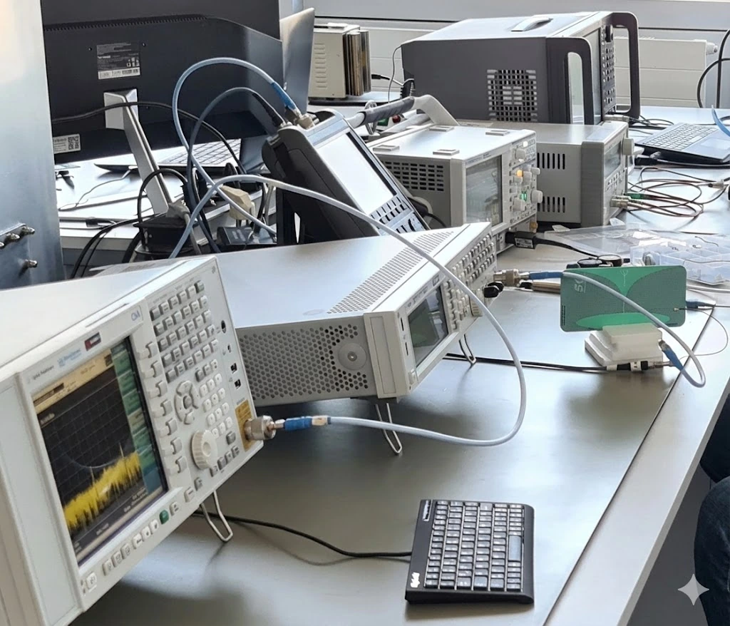
Our Munich laboratory combines electromagnetic simulation with RF measurement and prototyping, allowing us to compare the design directly with the physical product.
DIGITAL LABORATORY
Tools matched to the development task.
3D EM simulation: ANSYS HFSS and CST Microwave Studio for antennas, enclosures, coupling and RF transitions.
Circuits and PCBs: ANSYS Designer and Altium Designer for RF circuit analysis, circuit diagrams and PCB layout. AutoCAD supports mechanical design and manufacturing documentation.
Measurement automation and analysis: MATLAB for instrument control, data processing and comparison of measurements with simulations.
Experience with other tools: ADS/Momentum, AWR Microwave Office, FEKO, Sonnet, IE3D, Ensemble, Optimetrics and Mathcad. We select the environment according to the task, required method and project licence.
RF LABORATORY
Measure RF performance.
We tailor the measurement setup, calibration, adapters and achievable uncertainty to the device under test. The stated instrument ranges are not a blanket commitment for every measurement quantity.
| Task | Equipment | Range | Measured parameters |
|---|---|---|---|
| Vector network analysis | Keysight P9375A | 9 kHz–26.5 GHz | S-parameters, matching, attenuation, isolation |
| Signal analysis | Agilent CXA | up to 26.5 GHz | Spectrum, signal levels, unwanted emissions |
| Signal generation | Agilent EXG X-Series | 9 kHz–6 GHz | RF test signals for assemblies and receivers |
| Noise measurements | Keysight N4000A / U7227A | Noise source: 10 MHz–18 GHz | Noise figure, gain and receive-path performance |
| Antenna measurements | Anechoic chamber | Dependent on the setup and antenna | Radiation pattern, gain and efficiency |
PROTOTYPING AND PRODUCTION
Rapid prototypes and repeatable production.
For prototyping, we use 3D printing, reflow and manual soldering of SMD and through-hole components, and mechanical integration models. We involve specialist manufacturing partners for PCB fabrication, CNC machining, laser processing and sheet-metal work.
Our project experience also includes RF transitions up to 90 GHz and a waveguide antenna at 200 GHz. These development tasks are distinct from the frequency range of our own instruments; any specialist measurements required are planned for the individual project.
YOUR REQUIREMENTS
Let’s discuss your RF signal path.
Frequency bands, available space, enclosure and performance targets are our starting point.